

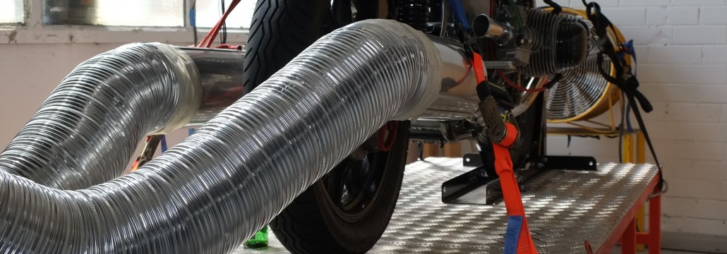
TThe dyno is almost complete. The Datamite 111 dyno system by Performance Trends is hooked up and loaded into the laptop and I have taken the first trial runs. All that remains is to calibrate the dyno and hook up the brake caliper. Oh, and the small matter of building a room around it!


The frame for the roller module gets a look-in now. The frame is made from 75x75x6 box section and will be eventually bolted to the floor. A bracket for the brake calliper was fabricated and the pillow block bearings are standard 60mm UC212 units. The deck is 5mm aluminium chequerplate.

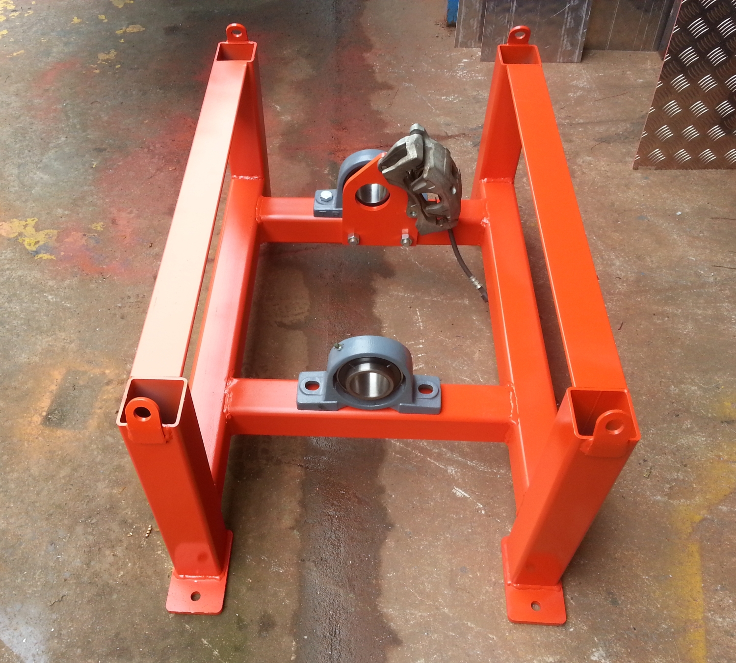

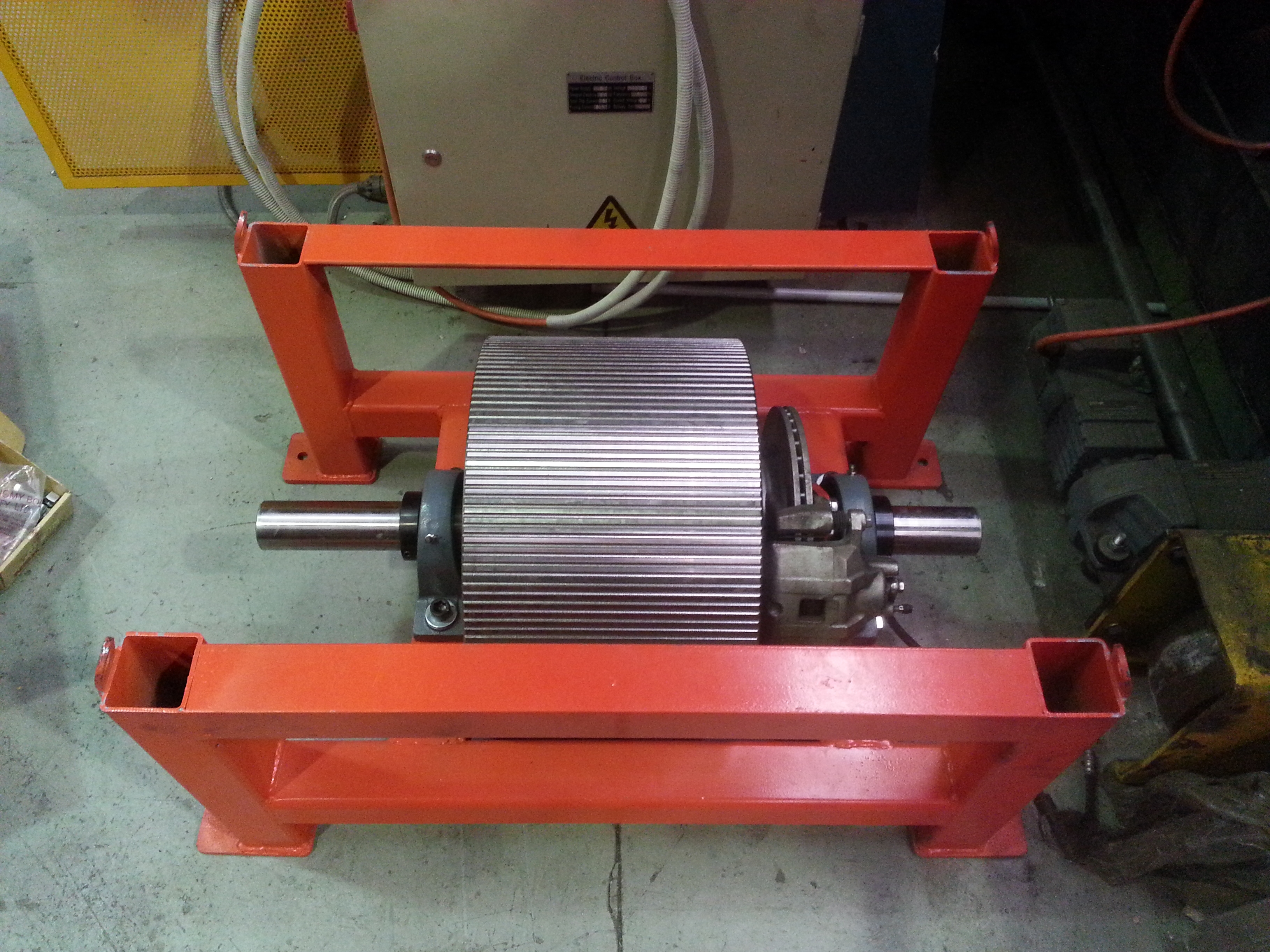
The bearings are induction heated and slipped over each shaft end, then the assembly is lowered into the completed frame.


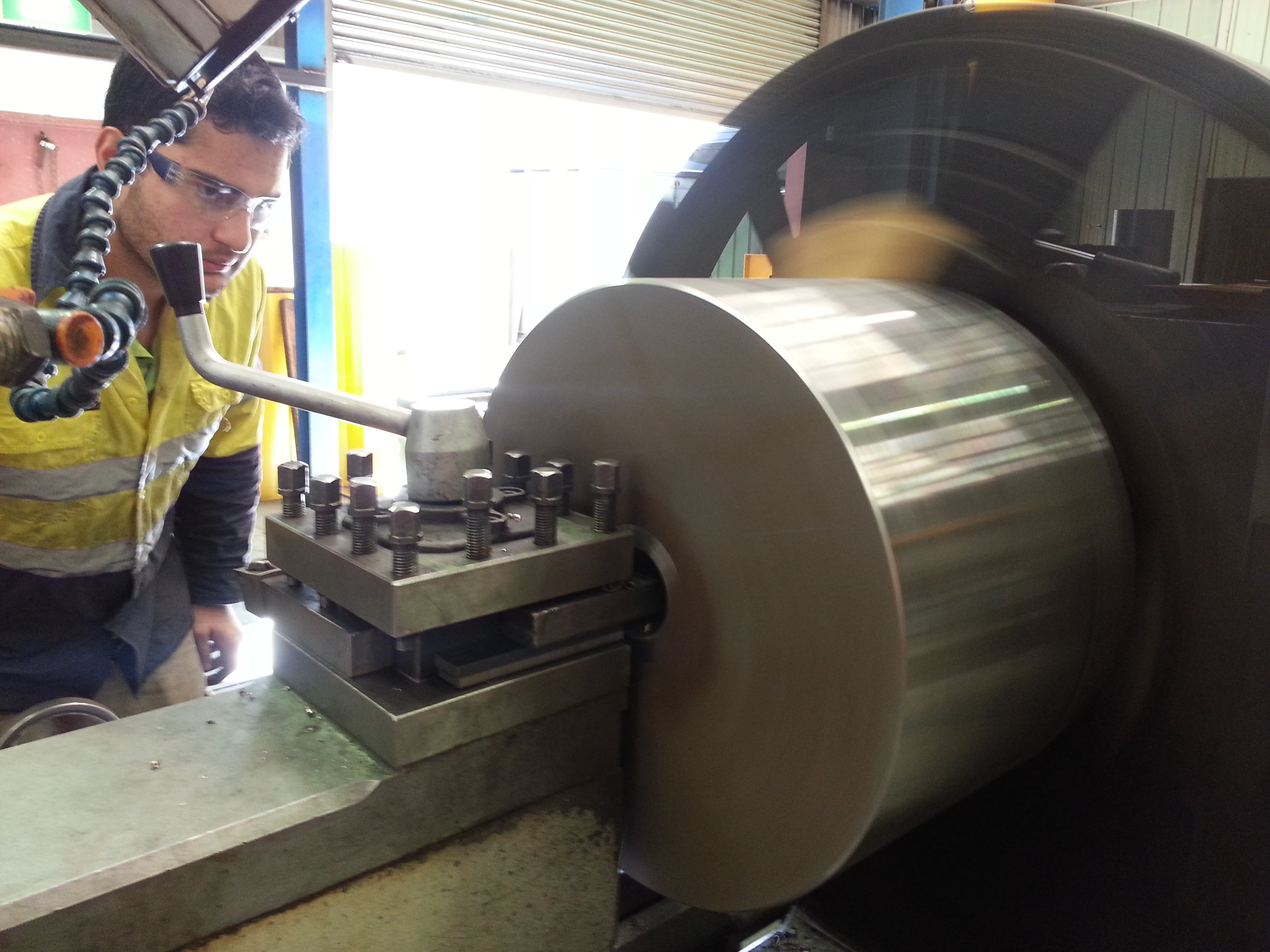
Now that the shaft has been shrunk into the roller, the assembly goes into a CNC lathe to take a lick off the O.D. and to machine cross grooves using the live tooling of the machine.
Not many dyno rollers have this feature (usually heavy knurl instead) and I’m exceedingly lucky to have access to these facilities.


The dyno roller starts off with a raw hunk of K1045 steel, 460mm in diameter and weighing 400kg. Some people turn down each end to form stub axles, but in my case, the shaft is quite long so this is not feasible. Instead, the shaft will be made separately and shrunk into the lump.

Drilling pilot hole
Boring to final ID
Next, the shaft was turned up. By design there’s almost 0.1mm (4 thou) interference between the shaft and the bore!! How the hell are we going to get this puppy in? With extreme heat and cold of course. As the ‘hot’ shaft set a bath of liquid nitrogen furiously boiling, I started heating the lump with a very large blow torch. After 20 minutes, the boiling stopped, signalling that both liquid and metal were at the same temperature: -196C or -385F.
But the lump still needed lots more heating before there would be enough clearance between the shrunken shaft and the expanded lump to safely insert the shaft. The time came to insert the shaft – a tense moment: if we hadn’t got it right, the shaft could sieze part we down creating a very big headache. After shaft and lump were united and allowed to equalize with ambient temperature, they were as good as one piece of metal.

The sword of damocles

freezing and heating

Tense moment!

In!!

TThe lump has a polar moment of inertia of 10.07 m^2 kg. So your average airhead should produce a run of around 10 seconds in 4th gear. If successful at getting around 90hp at the back wheel of the salt racer then runs will need to be done in top gear. In which case, that 415kg wheel will be spinning at around 2600RPM. All this is theoretical. It’ll be interesting to finally see how close to reality my maths is!
Here’s a drawing of the wheel.

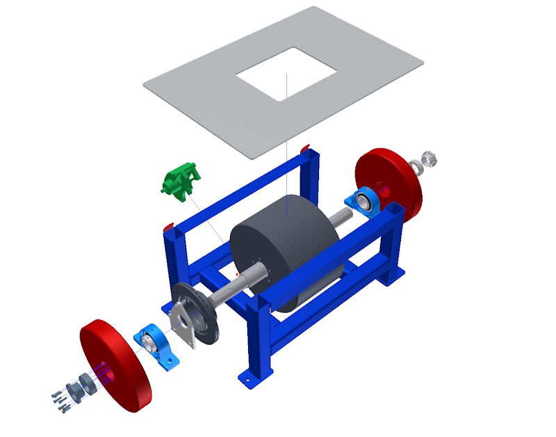
here’s an exploded view of the dyno design. The main wheel has been sized to suit the types of bikes that I will be testing: bikes from the 70’s and 80’s, mainly airheads. The red wheels are removeable and can be installed to cater for bikes with more horsepower. A disk brake is incorporated to save the bike’s rear brake. Also, there is plenty of room for a motor and electric clutch to be installed at a later date so that the wheel can be used to start race bikes.

I usually do what the voices in my partner’s head tell her to tell me to do.
For once, my own head had something to say: ‘Stop wishing you had a dyno and build one! You’re a k’n engineer for Heaven’s sake!’ And so it started….
There are two types of dyno: the inertia or rolling road and the break dyno (the break dyno is responsible for the term ‘Brake Horse Power’). There are pro’s and cons for both but the big plus for the inertia type is that it is the easiest and cheapest to build. Other pluses: More closely replicates what the bike experiences on the road and results from pull to pull are more consistent and repeatable. Repeatablility is key when you are checking whether your random fiddlings are having the desired effect.
The inertia dyno is comprised of two basic parts: a rolling mass that is accelerated by the rear wheel of a motorcycle and a software package that crunches the numbers to spit out torque/power curves.
Mr Newton worked out the relationships that are used by the software which in essence deals with the rate at which your motorcycle accelerates a mass of known polar moment of inertia.
There’s heaps of DIY dyno stuff on the web if you want to dig deeper, here’s a couple:
DTEC inertia dyno design guide
The design is all but complete and I’ll be looking at design considerations in more detail in the next blog..