


Images: With the kind permission of Jon-Lars Sorenson. More pics at: http://s44.photobucket.com/user/R90S/library/
When designing exhaust systems for race engines, I pit a couple simulation programs against eachother. This has proved to yield pretty good base designs from which dyno tuning takes over: a complex world of interactions including the tricky relationship between exhaust design and inlet tract design. The whole system can be likened to a double ended pipe organ with the inlet and exhaust valves as keys – it is literally akin to tuning a musical instrument.
All well and good to put this sort of effort into shaving half a second off a racing lap time, but for your average rider on a street bike with its wide operating parameters, moderate departures from design optimals will be lost in the noise. The calculated base design should be good enough. Besides, packaging contraints will often have you deviating from design ideals, in which case the exercise may instead become a matter of avoiding lengths and diameters that actively rob horsepower where you want it. This is particularly true of the ‘tail-pipe’ length which includes the collector length (downstream of the merge) and the muffler length.
For the calculated tail-pipe lengths to work, the muffler should be a straight-through absorber type of the same internal diameter as the collector. Unfortunately, the optimal overall tail-pipe length is influenced by the individual muffler characteristics and its length. So the tail-pipe lengths below are a rough guide only. Anyway, let’s be honest, half the time we choose mufflers for their looks and sound right? Call that ‘ego contraints’, which leads to the following fromula:
Wide operating/operator parameters + packaging constraints + ego constraints = big fat compromise!
This is the world most of us inhabit. Unless you confuse the street for a racetrack and go to considerable extra effort in dialing out contraints and other unknowns for a narrower set of riding parameters, then quit obsessing over mm’s! (from an ex mm-obsessive).
With the above firmly in mind, here’s a set of street calcululations for a stock R100. Caveat: I haven’t built and tested this street system. But the following guidlines should yield better performance than the stock exhaust system and probably better than some of the dodgier after-market 2into1 offerings – particularly the ones that have one pipe butting into the other without a well designed merge.
Main Inputs (among others):
Compression ratio: 8.7
Volumetric efficiency: 0.95 (assumed)
Stock 308 cam duration @ 0.05″ lift: 243 deg
RPM at peak power: 6800
Application: street peformance – tuning for mid range torque and higher RPM HP
Resulting 2into1 specs:
1) Header diameter – stick to stock 38mm* pipe size even for warmer 336 or 324 cams with longer durations.
2) Header pipe length: 770 – 835mm (Third harmonic: the magic 32″!) err on longer side for our air cooled machines and approx 50mm longer if have warmer cam. **
3) Into a collector via a well designed merge.
4) Collector pipe size: 44 – 48mm (1-3/4″ or 1-7/8″)
5) Best tail-pipe lengths including collector and ‘straight through’ absorber style muffler: 435, 870, 1740 mm*** (4th, 3rd and 2nd harmonic repectively – 4th is the best)
6) Worst (power robbing) tail-pipe lengths: 650, 1300 mm
* All pipe sizes based on OD and 1.6mm (1/16″) wall thickness
** Ideally, both headers to be same length
*** Tail pipe lengths vary depending on type and length of muffler.
The header, or primary pipe lengths should idealy be the same. Though you are not going to notice moderate deviations (which may actually help spread the torque curve a little). This is most easily achieved by symetrically dropping both pipes back under the sump into a merge towards the back of the engine. Though some clearance is lost, this configuration is considered efficient because it minimises the number of bends.
Alternatively, it’s off to the same side for both pipes with chichanes in the near side pipe to even the lengths. Jon Lars Sorenson’s bike sports a fine example – see pic below.
Then there is the merge (or y-piece). Yep, there are good and bad designs. Try the search: ‘merge collector design’
And some advice to you cafe dudes: Presumably, if you are reading this then you care about performance? If in tandem with this exhaust system you are also thinking of replacing the stock air intake system with nothing but a pod filter… Dont!
Happy fabbing.
Adrian


Finally getting to the meaty end of the salt racer build.
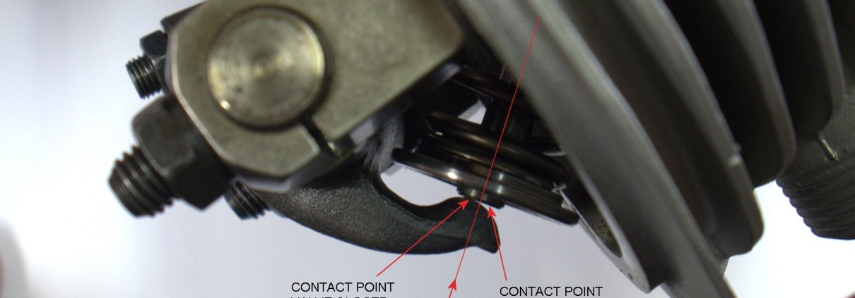
While the crank is off getting balanced with the new pistons and rods, I had a look at the rocker geometry.
With the high lift cam (about 12mm at the valve) and recessed valve seats the geometry did not look good. With valve fully closed, the rocker nose was close to the edge of the valve stem end and moved just past the valve stem centerline at full lift. Not the best. Ideally, the nose travel across the stem end should be equidistant about the valve stem certerline.
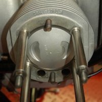
The only way I could think to adjust this was to adjust the thickness of the spacers under the rocker posts. The stock item is 3mm. Replacing it with a 1.5mm spacer got things right as shown in the pic but only for that rocker! All the others were a bit different but acceptable with the 1.5mm spacer.
A stock pushrod was transmogrified into an adjustable one so that I could determine the correct length for the pushrods. I was going to have a shot at making my own tapered aluminium ones but just don’t have the time so it’s off to the pushrod man to have some made in 4130.


Here’s a quick rundown of the process I went through in sorting the rear suspension geometry of the salt racer.
First task was to calculate the shock specifications. I started manually calculating these with the help of a couple texts including Tony Foale’s tome on the subject: Motorcycling Handling and Chassis Design. Even though the salt racer’s geometry is relatively simple compared to modern sports bikes with all their tricky linkages, I soon gave up and bought Tony’s program: Motorcycling Analysis which is basically the book in program form – this made things very much easier with the luxury of being able to easily experiment. Highly recommended. www.tonyfoale.com
I’m not going to describe the process in detail but after inputting the geometry of the airhead frame + oilhead swingarm, I arrived at the following specifications for the shock (which ended up being similar to the stock R1100RT shock):
Free length: 340 (fully extended)
Travel: 50mm
Spring rate: 190N/mm
Lower clevis to suit the R1100 swing arm.
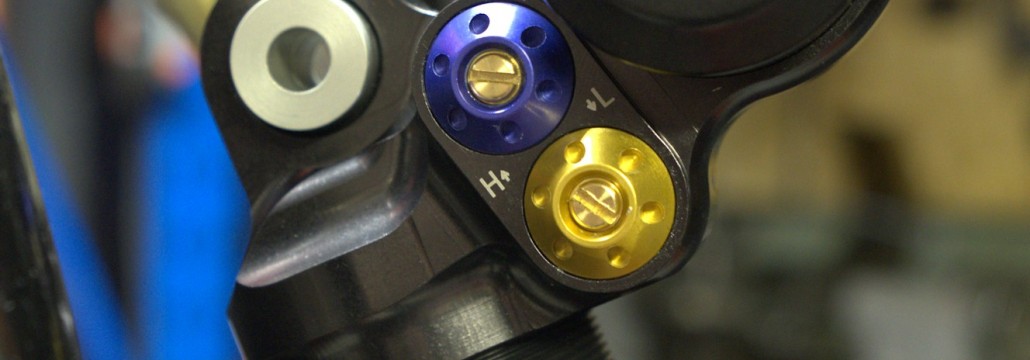
I opted for Hyperpro and soon after, a very sexy looking piece of Dutch bling landed on the doorstep complete with damping adjust both ways and ride hide adjust.
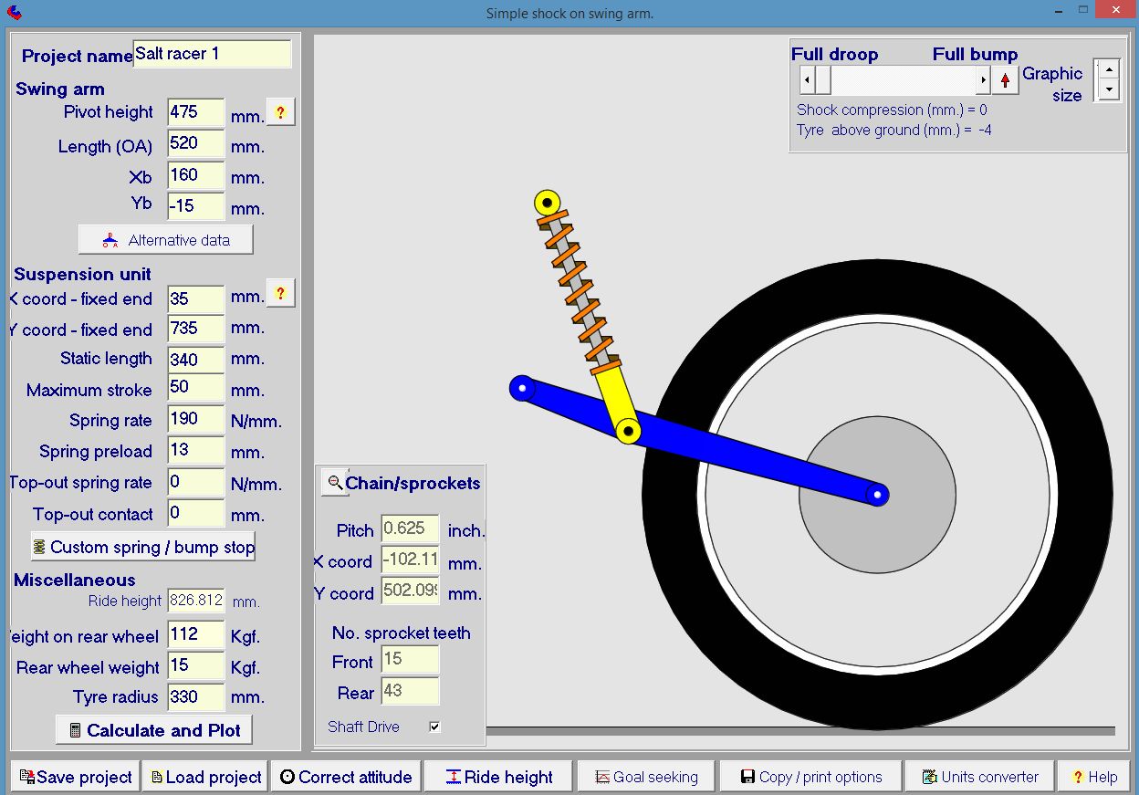
The program was used to predict the behavior of the system and tweek certain parameters so that ideal suspension characteristics were obtained – in this case we were shooting for a total sag (bike + Rider) of between 25-30mm with a spring preload of no more than 15mm. Most the program parameters as defined in the program’s set up page below are locked in: The oilhead swing arm dimensions cannot be changed, nor can the spring specifications. The only parameters that can be changed are the ‘X coord’ and Y coord (which locate the top fixed end of the shock) and the spring preload. At this point we are mainly interested in the X coord and preload. The X coord is the horizontal mounting position of the shock in relation to the swing arm pivot. I took an educated guess at the back wheel load at 112kg with me as rider.
A few button presses revealed that a X coord of 35mm combined with a spring preload of 13mm gave a total sag of 28mm. You can see the 35mm of X coord in the scaled graphic: the top end of the shock is just behind the swing arm pivot. A spring preload of 13mm is a little on the high side for this particular spring. I could have reduced the necessary spring preload to get the target sag by pushing the top of the shock futher behind the swingarm pivot e.g. X coord of 40 or 50mm but there were other reasons why this was not so practical including complicating the mounting arrangement to the frame. So a X coord of 35mm was settled upon. Now the Y coord could be tweaked, but this was done on the bike with shock attached to swingarm – more of this later.
Here’s the setup page of Tony’s program showing all the vital suspension stats of the salt racer. BTW, this is only the rear suspension part of the program. You could go on to model the entire suspension behavior of a bike if you so wished.
The following is one of the many graphs that Tony’s program spits out. It shows shock displacement V’s wheel movement. The point to note is that from a completely unloaded state, the sag under full load (rider plus bike) is 28mm (vertical black line). Remember, nobody has sat on a bike yet, we are using the program to predict what the suspension will do in order to best locate the fixing point for the top end of the shock to the frame.
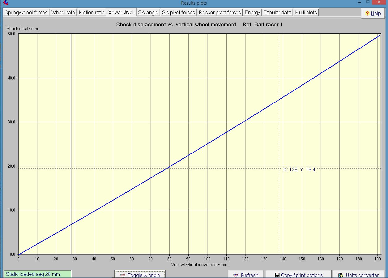
Another interesting graph is the effective spring rate measured at the wheel or ‘wheel rate’ Notice that even though the spring has a linear rate, the effective wheel rate is progressive ranging from approx 12 – 18 N/mm. This is the reason that people shouldn’t blindly ‘upgrade’ their linear springs to progressive rate springs. The suspension geometry may already be designed to obtain a progressive effective rate at the wheel with a linear spring. This is particularly the case for modern bikes with complex suspension linkages.

So, having pegged the X coord at 35mm aft of the swing arm pivot, next job was to work out the vertical co-ordinate from the ground of the shock mounting position to the frame (Y coord). With a shaft drive, what we want to happen is this: when the bike is fully loaded, the gearbox output shaft axis, drive shaft axis and center of the rear wheel are all on the same straight line. This ensures that any mechanical inefficiencies from universal joints operating at angles are dialed out – particularly for the salt racer where I’m chasing every microhorse. In reality, of course, this straight line position will become the median about which the suspension moves.
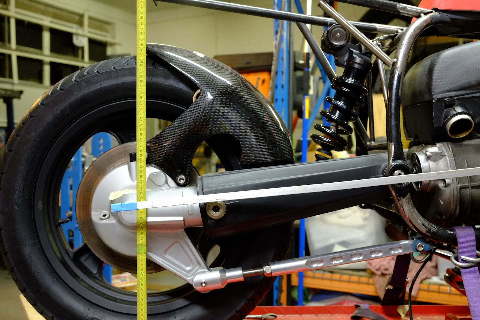
The image below shows the bike in an unloaded state (bike supported by jack under oil pan). The top edge of the bar with the blue tape marks the position where the drive train is perfectly aligned. With the top of the shock unattached, the bike was jacked up so that the center of the wheel was approx 25-28 mm below the top top edge of the bar. With top of shock 35mm aft of the swing arm pivot (Y coord) we now had the mounting position of the shock to the frame. I then mocked up a temporary mounting arrangement to lock the shock into this position. So, theoretically, with rider aboard the suspension should sag by the predicted 25-28mm at which point the drive train becomes aligned…
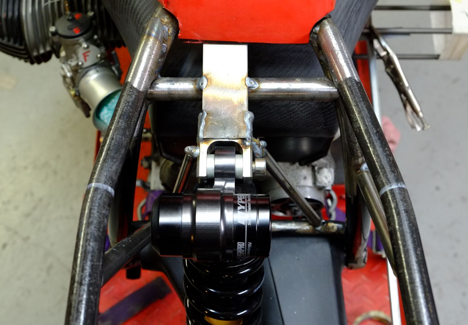
Now to test our predictions! With shock firmly fixed to the frame I hopped on board. The measured total sag was 21mm. Not bad! I didn’t expect it to be spot-on because the bike was not complete and therefore under it’s finished weight. But it’s in a workable ball-park, there is enough adjustment in the system – adjustable torque arm and ride height adjust on the shock – to tweak from this point so the next step is to remove the temporary bracketry and properly build in the top of the shock. To be continued….


Here’s a method that involves little math compared with the conventional method as described here
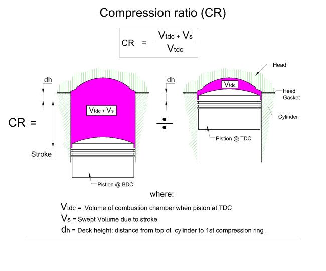
The following method involves bolting the head and cylinder together as an assembly on the bench using all-thread. Then carefully placing the piston in the cylinder at exactly where it would be if it were at top dead center (TDC) in an assembled motor. The volume of the combustion chamber (Vtdc) can then be measured directly with the burrette. It’s then simply a matter of dividing this volume into the entire volume above the piston at bottom dead center (BDC) to determine the compression ratio as illustrated in the diagram below.
Step 1. Determine piston position at TDC: We do this using the scribed line on the feeler gauge that was used in method 1 to determine the deck height ‘dh’ and repeated her:
To measure dh, clamp the cylinder to the block using tubes on the studs, turn the motor via the back wheel or an 8mm allen key on the alternator rotor bolt to until the piston is at TDC. Slide a squared off 0.1mm feeler gauge between the cylinder wall and piston so that it rests on the 1st compression ring. Use a very pointy scribe to mark the top of the cylinder – some prussian blue would be handy here. Make sure you slide the gauge in line with the horizontal axis of the gudgeon pin (ie at 3 and 9 o’clock looking directly at the piston) as this is where piston rock is at a minimum. If excising care, you can measure dh with this method to within +/- 0.1mm.
Bolt cylinder to case using tubes
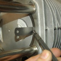
Scribe line with piston at TDC

Step 2. Off to the bench: Move cylinder off the bike and onto the bench then carefully place the piston at TDC using the scribed line on the feeler gauge. Grease the rings a little first in order to make things water tight. Before bolting everything together, use a vernier caliper to take a checking measurement from the bottom of cylinder skirt to the bottom of the cylinder to give a means of checking that the piston hadn’t moved position after bolting everything together and buggerising around.
Step 3. The bench top assembly: Bolt cylinder, gasket and head together using 10mm all-thread then use checking measurement at Step 2 to check that piston hadn’t moved during the bolt up.

Using scribed line to set piston to TDC
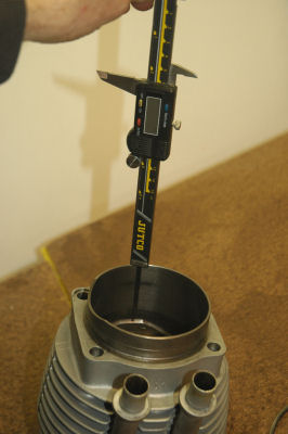
Taking measurement to skirt bottom

Bolting it all together
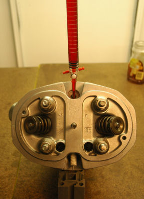
Step 4. Measuring the combustion chamber volume (Vtdc) with a burrette: If you examine a head you’ll, see that when the plug hole is vertical, a part of the outer periphery of the chamber is higher than the bottom of the plug hole and around a corner a bit like under the lip of a toilet bowl. So if you fill when the plug hole is vertical, a sizable air pocket will form at this higher peripheral part.
The way to get around this is to first fill to the bottom of the plug hole with the cylinder vertical on the bench. This allows the peripheral volume to completely fill. Then, tilt the assembly so that the plug hole is vertical and continue filling until the fluid level just reaches the bottom of the plug hole.
BTW: The burette is the cheaper acrylic type (100ml) and cost me $27.00. Graduations are 0.2ml. (The glass ones are over $100). Use water with food colour.

Final filling with plug hole vertical
ditto
So the final number for my particular R100 BMW airhead? Combustion chamber volume Vtdc = 66.7 cc’s (or ml).
Step 5. Calculating CR: All that remains is a fairly simple calculation. In the case of my particular R100 airhead: Stroke = 70.6mm and bore = 94.25mm (first oversize)
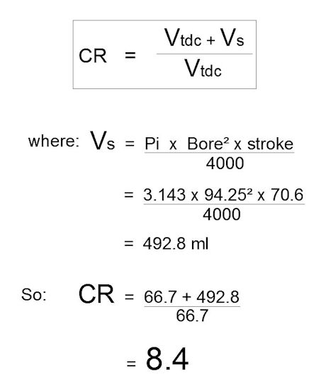
Not terribly high for a large valve early 80’s R100 that supposed to be 9.5… but that’s another story…
