Airhead salt racer rear suspension geometry
Here’s a quick rundown of the process I went through in sorting the rear suspension geometry of the salt racer.
First task was to calculate the shock specifications. I started manually calculating these with the help of a couple texts including Tony Foale’s tome on the subject: Motorcycling Handling and Chassis Design. Even though the salt racer’s geometry is relatively simple compared to modern sports bikes with all their tricky linkages, I soon gave up and bought Tony’s program: Motorcycling Analysis which is basically the book in program form – this made things very much easier with the luxury of being able to easily experiment. Highly recommended. www.tonyfoale.com
I’m not going to describe the process in detail but after inputting the geometry of the airhead frame + oilhead swingarm, I arrived at the following specifications for the shock (which ended up being similar to the stock R1100RT shock):
Free length: 340 (fully extended)
Travel: 50mm
Spring rate: 190N/mm
Lower clevis to suit the R1100 swing arm.
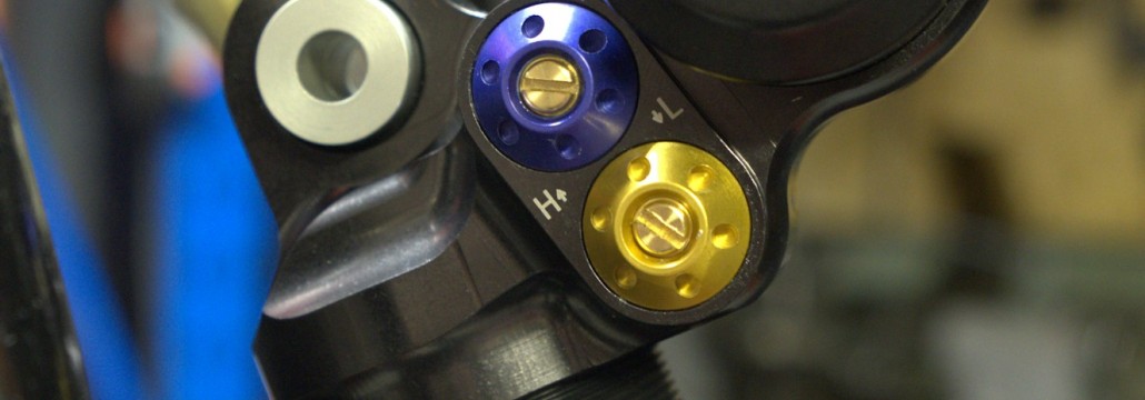
I opted for Hyperpro and soon after, a very sexy looking piece of Dutch bling landed on the doorstep complete with damping adjust both ways and ride hide adjust.
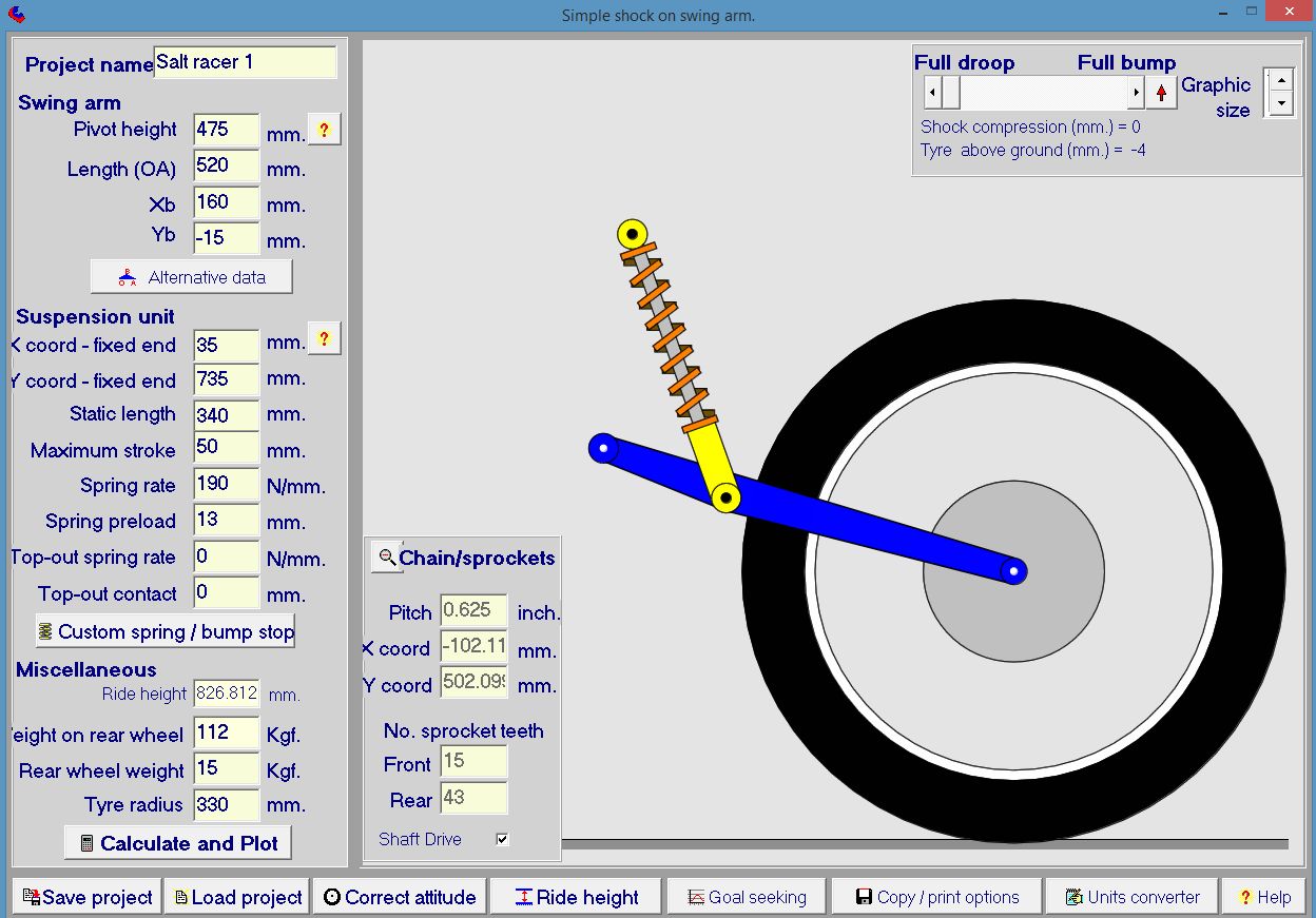
The program was used to predict the behavior of the system and tweek certain parameters so that ideal suspension characteristics were obtained – in this case we were shooting for a total sag (bike + Rider) of between 25-30mm with a spring preload of no more than 15mm. Most the program parameters as defined in the program’s set up page below are locked in: The oilhead swing arm dimensions cannot be changed, nor can the spring specifications. The only parameters that can be changed are the ‘X coord’ and Y coord (which locate the top fixed end of the shock) and the spring preload. At this point we are mainly interested in the X coord and preload. The X coord is the horizontal mounting position of the shock in relation to the swing arm pivot. I took an educated guess at the back wheel load at 112kg with me as rider.
A few button presses revealed that a X coord of 35mm combined with a spring preload of 13mm gave a total sag of 28mm. You can see the 35mm of X coord in the scaled graphic: the top end of the shock is just behind the swing arm pivot. A spring preload of 13mm is a little on the high side for this particular spring. I could have reduced the necessary spring preload to get the target sag by pushing the top of the shock futher behind the swingarm pivot e.g. X coord of 40 or 50mm but there were other reasons why this was not so practical including complicating the mounting arrangement to the frame. So a X coord of 35mm was settled upon. Now the Y coord could be tweaked, but this was done on the bike with shock attached to swingarm – more of this later.
Here’s the setup page of Tony’s program showing all the vital suspension stats of the salt racer. BTW, this is only the rear suspension part of the program. You could go on to model the entire suspension behavior of a bike if you so wished.
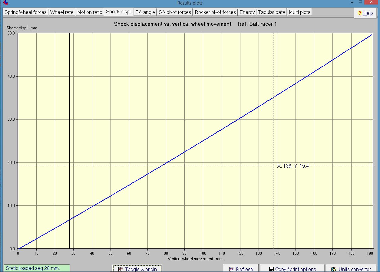
The following is one of the many graphs that Tony’s program spits out. It shows shock displacement V’s wheel movement. The point to note is that from a completely unloaded state, the sag under full load (rider plus bike) is 28mm (vertical black line). Remember, nobody has sat on a bike yet, we are using the program to predict what the suspension will do in order to best locate the fixing point for the top end of the shock to the frame.
Another interesting graph is the effective spring rate measured at the wheel or ‘wheel rate’ Notice that even though the spring has a linear rate, the effective wheel rate is progressive ranging from approx 12 – 18 N/mm. This is the reason that people shouldn’t blindly ‘upgrade’ their linear springs to progressive rate springs. The suspension geometry may already be designed to obtain a progressive effective rate at the wheel with a linear spring. This is particularly the case for modern bikes with complex suspension linkages.
So, having pegged the X coord at 35mm aft of the swing arm pivot, next job was to work out the vertical co-ordinate from the ground of the shock mounting position to the frame (Y coord). With a shaft drive, what we want to happen is this: when the bike is fully loaded, the gearbox output shaft axis, drive shaft axis and center of the rear wheel are all on the same straight line. This ensures that any mechanical inefficiencies from universal joints operating at angles are dialed out – particularly for the salt racer where I’m chasing every microhorse. In reality, of course, this straight line position will become the median about which the suspension moves.
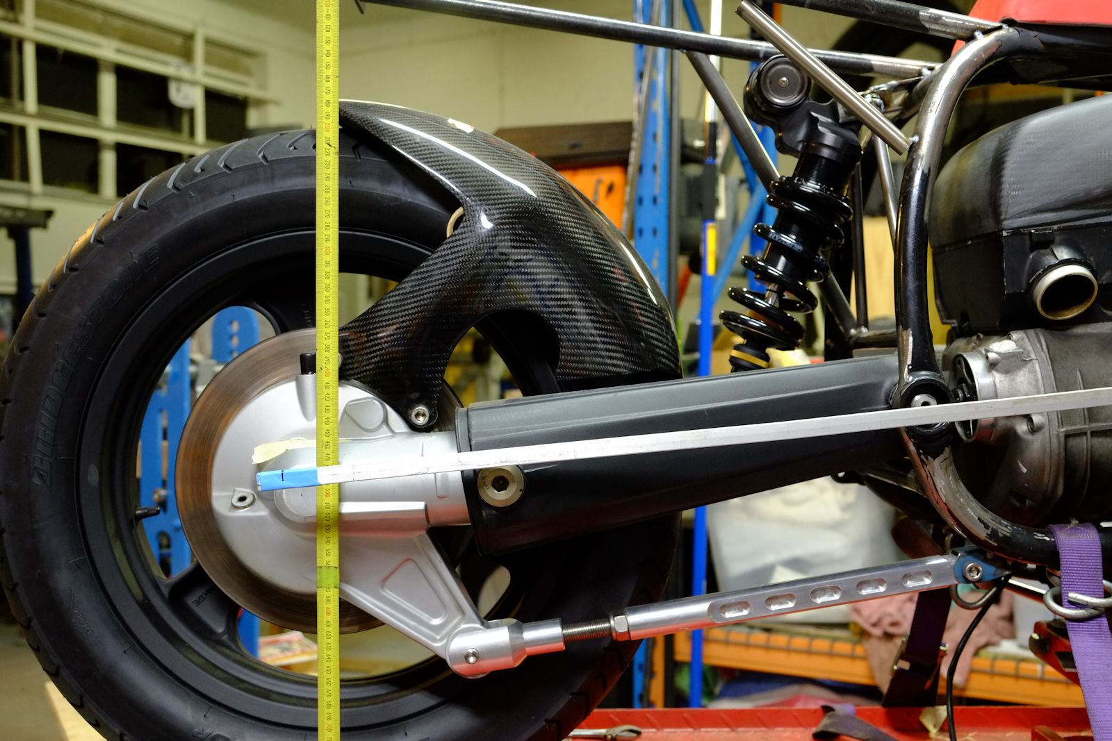
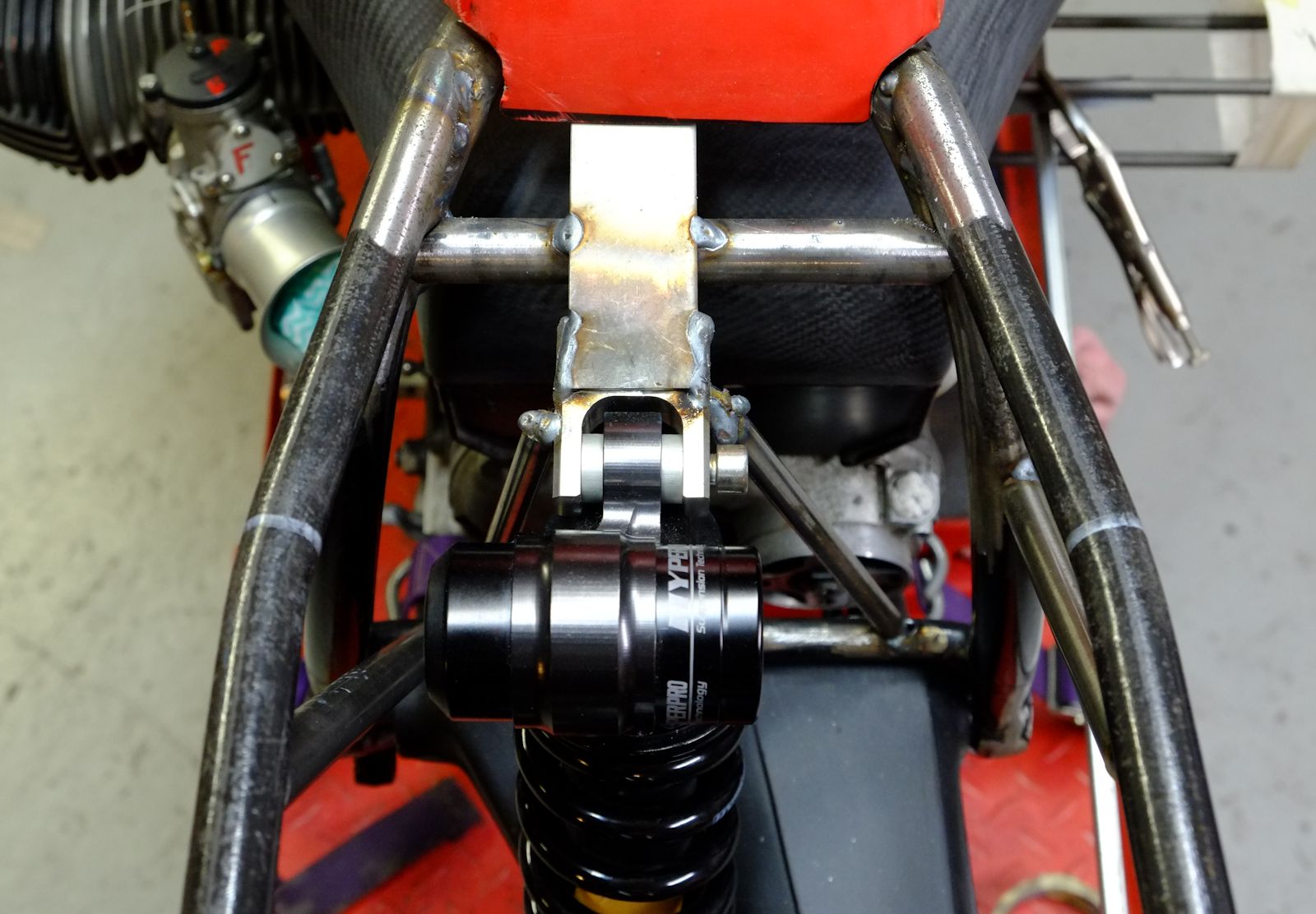
The image below shows the bike in an unloaded state (bike supported by jack under oil pan). The top edge of the bar with the blue tape marks the position where the drive train is perfectly aligned. With the top of the shock unattached, the bike was jacked up so that the center of the wheel was approx 25-28 mm below the top top edge of the bar. With top of shock 35mm aft of the swing arm pivot (Y coord) we now had the mounting position of the shock to the frame. I then mocked up a temporary mounting arrangement to lock the shock into this position. So, theoretically, with rider aboard the suspension should sag by the predicted 25-28mm at which point the drive train becomes aligned…
Now to test our predictions! With shock firmly fixed to the frame I hopped on board. The measured total sag was 21mm. Not bad! I didn’t expect it to be spot-on because the bike was not complete and therefore under it’s finished weight. But it’s in a workable ball-park, there is enough adjustment in the system – adjustable torque arm and ride height adjust on the shock – to tweak from this point so the next step is to remove the temporary bracketry and properly build in the top of the shock. To be continued….





Leave a Reply
Want to join the discussion?Feel free to contribute!