airhead salt racer gets stiffed!

TThere’s a certain satisfaction in hacking tons of detritus and redundant bits off a frame – a bare canvas on which to plonk your own detritus and redundant bits!

Effectionally known as the ‘rubber cow’ the airhead frame is well known for it’s elastic nature.  BMW, in their wisdom, took the lengendary Norton Featherbed concept but rather than continuing each loop over the top and under the tank to the head stem, the BMW loops converge at a single spine that starts at the rear end of the tank and continues to the head stem.

This is where a good deal of the elasticity lurks…. and waits to be exited by the various pendulum effects from the front end and rear swing arm sections amongst other things.  I love a simplistic look but this can be hard to achieve. I could have gone the way that so many do and add tie rods that run from the head stem down across each side of the motor to the swing arm pivot area, but to my eye, this really stuffs up the simple lines of the bike.

I stood and stared and orbited around the frame for hours before settling on a stiffening plan and opted to horizontally stiffen the spine area and tie the top loops through to the head stem in a way that replicates the original Featherbed idea. Some gusseting of the head stem area was also added. Measuring and drawing in CAD for laser cutting makes things a whole lot easier.

airhead slat racer frame stiffening.


BMW airhead frame stiffenin

The oil cooler is a hand- me -down from my shed mate Ross’s Triumph Bonne salt racer build


laser_cut_frame_stiffening

laser cut stiffening plates


dyno deck

TThe deck frame is made from 40x40x3 angle and 40×3 box tube and the deck itself is 5mm aluminimum chequerplate. The legs can be bolted to the floor.

Dyno_frame1

Dyno_frame2

Dyno_instal1

dyno frame – the module

The frame for the roller module gets a look-in now. The frame is made from 75x75x6 box section and will be eventually bolted to the floor. A bracket for the brake calliper was fabricated and the pillow block bearings are standard 60mm UC212 units. The deck is 5mm aluminium chequerplate.

dyno_frame1

dyno_frame2

dyno_frame3

The bearings are induction heated and slipped over each shaft end, then the assembly is lowered into the completed frame.


dyno_boltup1

dyno_boltup2


dyno_boltup3

dyno roller – in the groove

Now that the shaft has been shrunk into the roller, the assembly goes into a CNC lathe to take a lick off the O.D. and to machine cross grooves using the live tooling of the machine.

Not many dyno rollers have this feature (usually heavy knurl instead) and I’m exceedingly lucky to have access to these facilities.

dyno_grooves1

dyno_grooves3

dyno_grooves4

raw dyno roller

Big lump ‘o’ steel

The dyno roller starts off with a raw hunk of K1045 steel, 460mm in diameter and weighing 400kg. Some people turn down each end to form stub axles, but in my case, the shaft is quite long so this is not feasible.  Instead, the shaft will be made separately and shrunk into the lump.

Drilling pilot hole

Drilling pilot hole


Boring to final ID

Boring to final ID

Next, the shaft was turned up. By design there’s almost 0.1mm (4 thou) interference between the shaft and the bore!!  How the hell are we going to get this puppy in? With extreme heat and cold of course. As the ‘hot’ shaft set a bath of liquid nitrogen furiously boiling, I started heating the lump with a very large blow torch. After 20 minutes, the boiling stopped, signalling that both liquid and metal were at the same temperature: -196C or -385F.

But the lump still needed lots more heating before there would be enough clearance between the shrunken shaft and the expanded lump to safely insert the shaft. The time came to insert the shaft – a tense moment: if we hadn’t got it right, the shaft could sieze part we down creating a very big headache.  After shaft and lump were united and allowed to equalize with ambient temperature, they were as good as one piece of metal.

The sword of damocles

The sword of damocles


freezing and heating

freezing and heating


Tense moment!

Tense moment!


It going!

In!!


The dyno roller

TThe lump has a polar moment of inertia of 10.07 m^2 kg. So your average airhead should produce a run of around 10 seconds in 4th gear. If  successful at getting around 90hp at the back wheel of the salt racer then runs will need to be done in top gear. In which case, that 415kg wheel will be spinning at around 2600RPM. All this is theoretical. It’ll be interesting to finally see how close to reality my maths is!

Here’s a drawing of the wheel.

Dyno_drum_dwg


dyno – exploded view

here’s an exploded view of the dyno design. The main wheel has been sized to suit the types of bikes that I will be testing: bikes from the 70’s and 80’s, mainly airheads. The red wheels are removeable and  can be installed to cater for bikes with more horsepower. A disk brake is incorporated to save the bike’s rear brake. Also, there is plenty of room  for a motor and electric clutch to be installed at a later date so that the wheel can be used to start race bikes.

BSA

BSA custom B33

salt racer

We’re off to the big white dyno at Lake Gairdner for speedweek 2015.

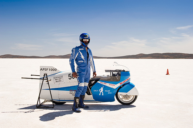
The image is of Brett Destoop, fastest man in Australia…… and the world in the APSF-1000 category. 232 MPH (371 km/h) Lake Gairdner. Thanks to Simon Davidson  for allowing me to feature his image. You can see more of  Simon’s work at his website.

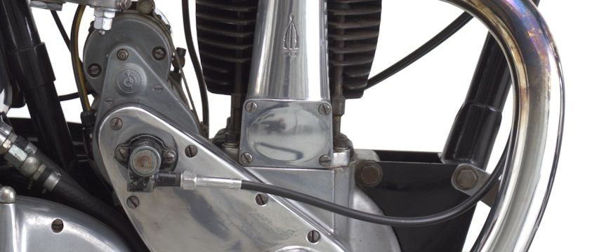
Skrunkworks will be campaigning Assalt – based on a 1987 BMW R80 with 1000cc  barrels and heads. We will be entering the 1000cc pushrod, unfaired (no streamlining), gasoline, category.

It’s hard to be realistic when your brain is pumped with the image of records shattering like glass as you scream across the salt… Thankfully, testosterone has settled back to default levels of egomania and sensible but vaguely irritating thoughts are invading like:  ‘Greater men and women have gone before…’  and   ‘this is going to be a 2+ year exersise...’

Update 03/07/2014: We are well underway working through the wish list put together in 2013 (below). Follow the progress on our blog or facebook or  instagram

  •  Gearing may be an issue: with a taller aftermarket  5th gear and the longest rear bevel drive available (32/11), we’ll probably need to spin the engine to 9000 RPM.
  • Cam: There was a time in the 1900’s that the only off-the-shelf ‘hot’ cam that you could get for an airhead was BMW’s own 336 ‘Sports’ cam. Things have evolved and now there are several modern grinds available – mainly out of Germany. I’ve got my eye on a 340 degree high end race cam…
  •  Crank will remain stock but balanced to lighter con-rods and light, high compression pistons. Static CR will be around 11:1
  • Lightened valve train throughout.
  • Inlet valves enlarged to 46mm.
  • Exhaust headers  enlarged to 41mm or more.
  • Heads ported to suit new valve sizes and dual plugged.
  • Dellortos – probably 40mm.
  • Modified oil pump to counter possible cavitation problems at high RPM’s
  • extend sump + oil cooler.
  • Wave tuned inlet and exhaust tract lengths.
  • Delete the alternator and run total loss ignition (starter can stay – weight is not such an issue since there is 3 miles to accelerate to speed)
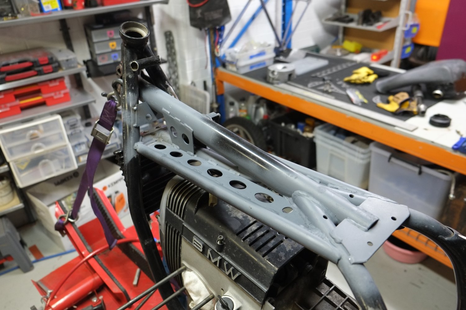
  • Stiffen the rubber cow’s frame – no tank slappers at +200km/h please.
  • Extending swing arm to improve straight line stability.
  • etc. etc – lots of them!

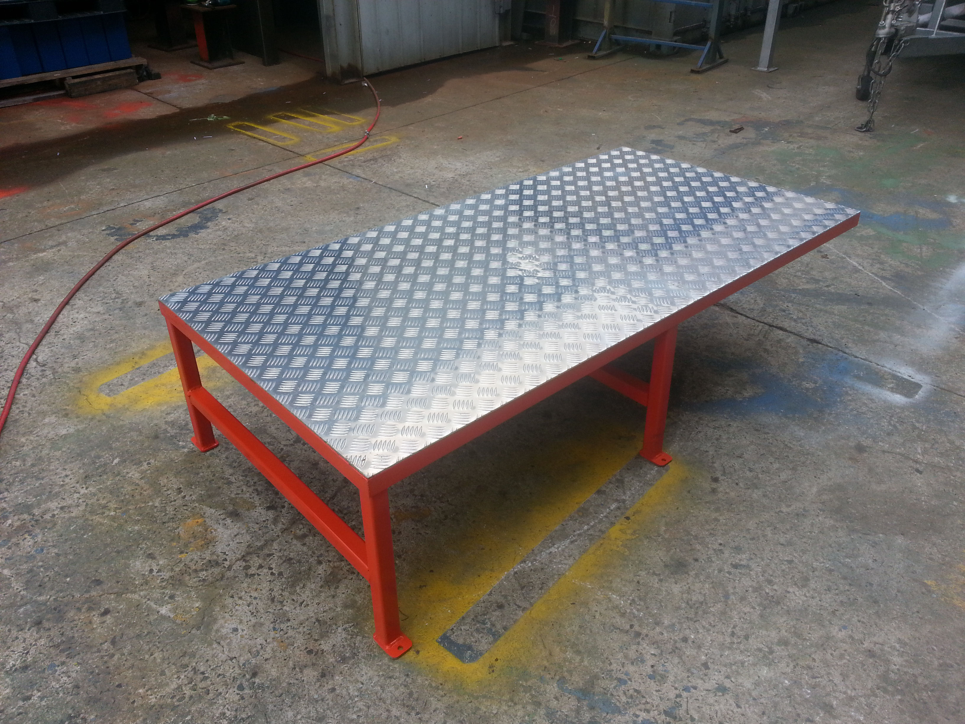
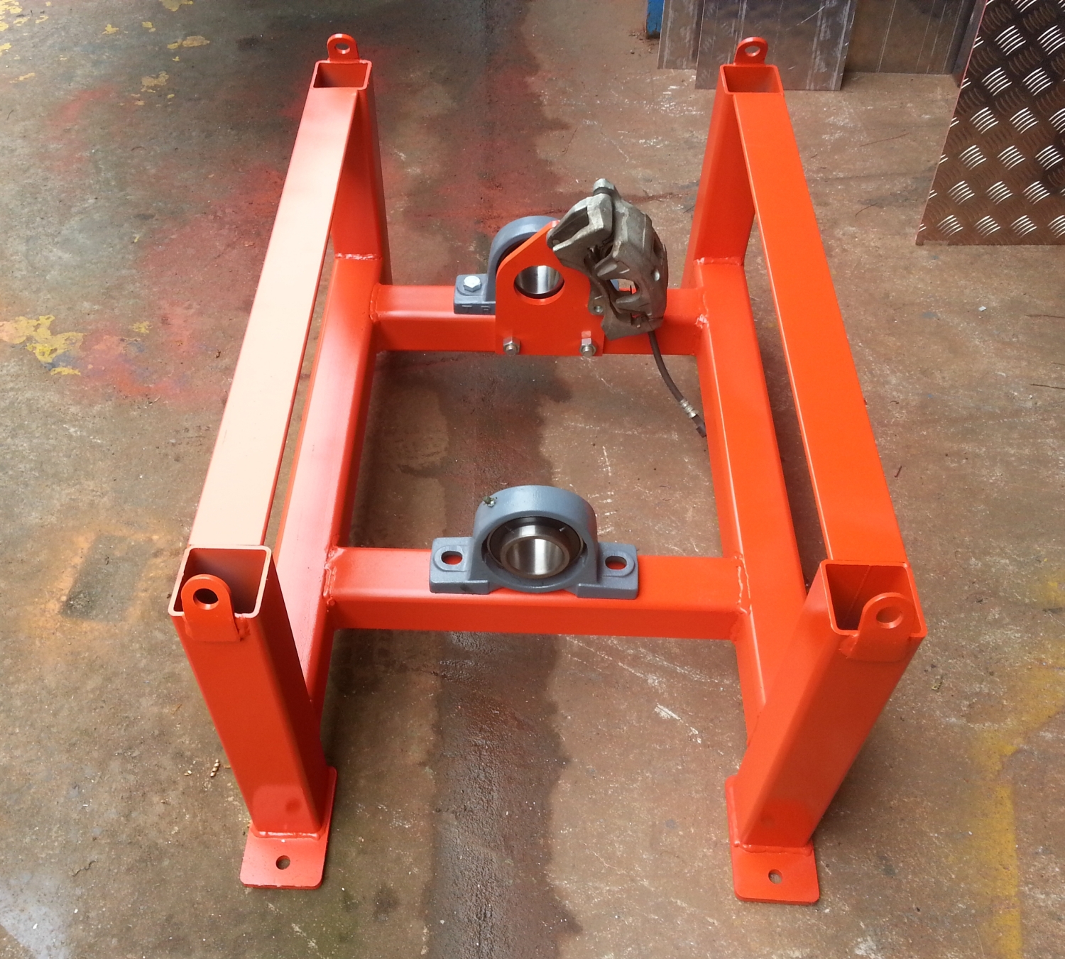
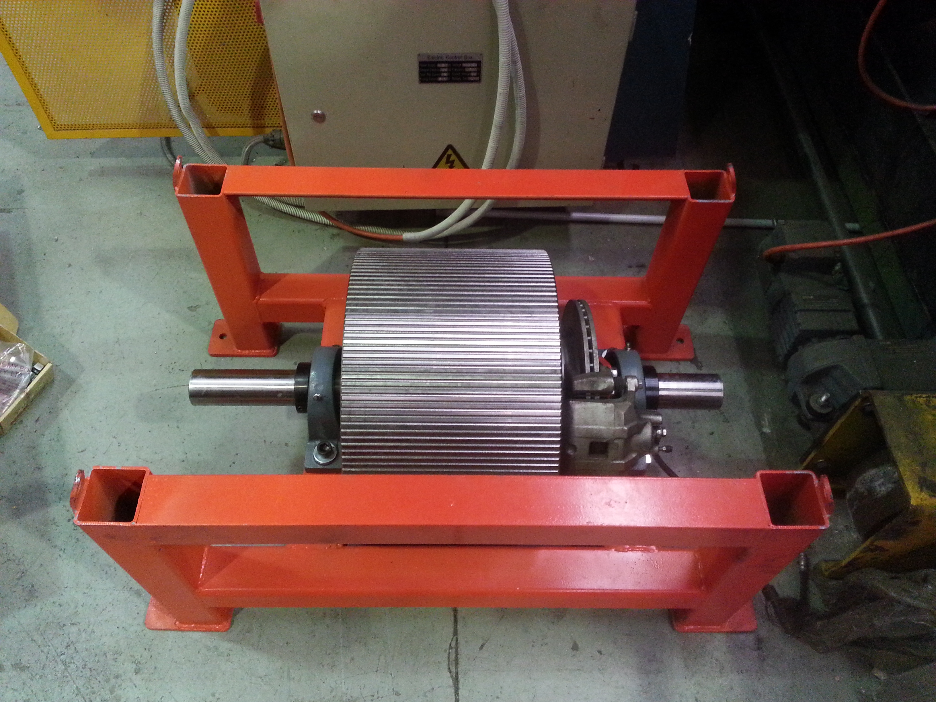
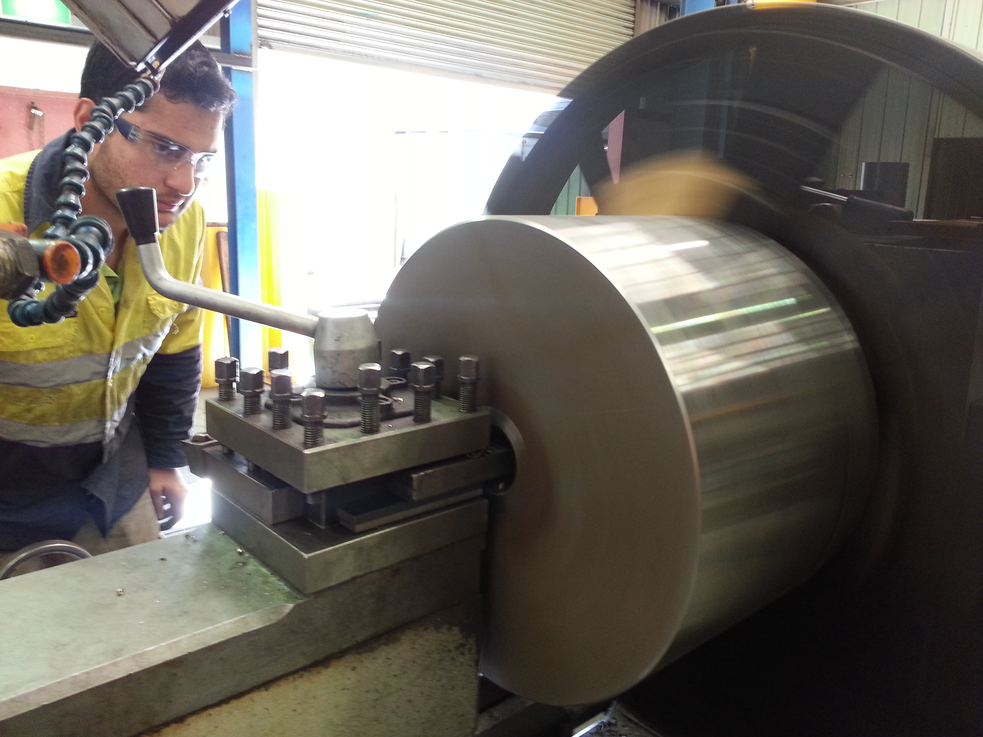
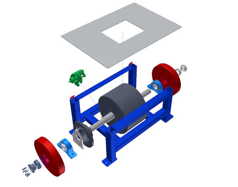
So, there’s lots to do including building the dyno and dyno room and it remains to be seen how we’ll fair leading up to the Feb 2015 crunch time, but one thing’s for sure, it’s going to be fun!

Update: 03/06/2014: Frame stiffening completed

My shed mate Ross of Supacustom has hooked up with an old compadre of mine, Paul Chiodo of  Peter Stevens Motor cycles.The pair will be campaigning a Triumph Bonne of noughties vintage.  Ross will be responsible for modifying the rolling chassis while Paul and his cohorts will be herding a bunch of wild horses through to the back wheel via various highly modified mechanical contrivances.

We’ve got heaps of work to do including building a dyno and dyno room! So strap yourselves in for an epic ride of a blog and PLEASE, leave comments and suggestions – doG knows we’ll need them!!

dyno – design

I usually do what the voices in my partner’s head tell her to tell me to do.

For once, my own head had something to say: ‘Stop wishing you had a dyno and build one!  You’re a k’n engineer for Heaven’s sake!’   And so it started….

There are two types of dyno:  the inertia or rolling road  and the  break dyno (the break dyno is responsible for the term ‘Brake Horse Power’). There are pro’s and cons for both but the big plus for the inertia type is that it is the easiest and cheapest to build.  Other pluses: More closely replicates what the bike experiences on the road and results from pull to pull are more consistent and repeatable. Repeatablility is key when you are checking  whether your random fiddlings are having the desired effect.

The inertia dyno is comprised of two basic parts: a rolling mass that is accelerated by the rear wheel of a motorcycle and a software package that crunches the numbers to spit out torque/power curves.

Mr Newton worked out the relationships that are used by the software which in essence deals with the rate at which your motorcycle accelerates a mass of known polar moment of inertia.

There’s heaps of DIY dyno stuff on the web if you want to dig deeper,  here’s a couple:

DTEC inertia dyno design guide

dynanometer-info.co.uk

The design is all but complete and I’ll be looking at design considerations in  more detail in the next blog..